
 My original ATTINY mini shield was a great idea in concept, and it worked as anticipated. However, since the mini shield was sooo small, it was a pain to make sure that it was lined up correctly on the arduino pins. There was a definite possibility to install it in the wrong pins and I didn’t want to find out what happened when it was plugged into the wrong pins. Here’s the mini shield:
So I decided to redesign the board, making it a little bigger so that it fully fills up 2 of the 4 banks of female pin headers on the Arduino. I’m hoping this will make it harder to screw up installing the shield onto the Arduino.
Since the board was going to be phyically larger, I thought I would also make it accept another ATTINY chip size. I arbitrarily chose a 14-pin ATTINY84 to accompany the 8-pin ATTINY85. The chip sockets are wired in parallel.
 There are 2 LED pins, the green one shows that power is recieved by the shield. The red LED is connected to each chips Pin 3, and is used for testing the chip. If you program a chip with the basic Blink Sketch, change the LED pin from Pin 13 to Pin 3. I added this LED for testing only.
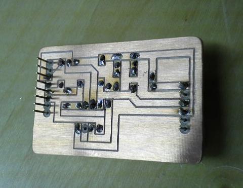
Here is a photo of the trace side of the board. I added more pins than were necessary so that the entire bank of female headers on the Arduino were filled. I removed the copper from around these unused pins so that there was no chance of shorting anything.
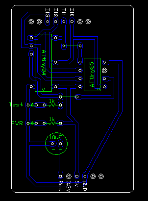
Here’s a screenshot of the trace layout. I use Draftsight to draw my boards. This view is of the component side of the board. The CAD dxf file is available below.
Download the DXF File (zip):
ATtinySheild-84-85-CTHrev2.zip