
 After recently finishing my ATTINY Programming Shield for Arduino Project, I was getting anxious to start trying to program some chips. Although I was eventually successful, this was definitely a learning experience. I will document what I did on this web page.
Here’s what I used:
Arduino Uno with ATmega168
Arduino IDE 1.0.1
ATTINY85 chip
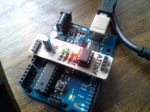
My DIY ATTINY programing shield (or breadboard)
NOTE: Instead of using a shield, you can use a breadboard: http://hlt.media.mit.edu/wp-content/uploads/2011/06/Screen-shot-2011-06-06-at-1.46.39-PM.png
UPDATE: Since Arduino 1.6ish, the instructions on this page are not valid. However, High-Low Tech has made an in depth how-to here:
STEP 1 – Software
The first thing to do is make a note where your Arduino sketchbook folder is. You can find this out by opening the Arduino IDE and going to File-Preferences. Close the Arduino IDE.
Navigate to your sketchbook folder. If you have a folder called HARDWARE, great, if not, create one.
Next, download the necessary files that will add the ATTINY chips to your Arduino IDE Tools-Board Menu. Download this zip file, unzip it.
http://hlt.media.mit.edu/wp-content/uploads/2011/06/attiny45_85.zip
Go into the extracted folder to attiny45_85/attiny45_85/cores/ and then move the attiny45_85 folder that is in the CORES folder into the HARDWARE folder in your sketchbook.
Open the Arduino IDE and make sure that there are new options available; an example is ATtiny85 (w/ Arduino as ISP). This is the one I’ll be using.
STEP 2 – Arduino as a Programmer
With the Arduino IDE open, connect your Arduino. Now select your options under Tools-Board and Tools-Serial Port. These will be the same as you normally use to program your Arduino, nothing new here.
Go to File-Examples and select ArduinoISP. Upload this sketch to your Arduino.
STEP 3 – Programming the ATTINY
Open the sketch that you want to upload to the ATTINY. Let’s assume you are uploading the blink sketch.
Go to Tools-Board and select your ATTINY chip. I’m selecting ATtiny85 (w/ Arduino as ISP).
Go to Tools-Serial Port and select your serial port, it should be the same as before.
Go to Tools-Programmer and select ARDUINO AS ISP.
Because the blink sketch is set up for the LED Pin to be Pin 13, you’ll have to change this to whichever pin the LED is hooked up to on the ATTINY. On my shield, this would be Pin 3.
At this point I was getting an error saying that OUTPUT was not defined. After doing a little searching online I found that adding:
#include <WProgram.h>
#include <Arduino.h>
to the sketch fixed the problem.
Upload the sketch and watch the ATTINY blink the LED!